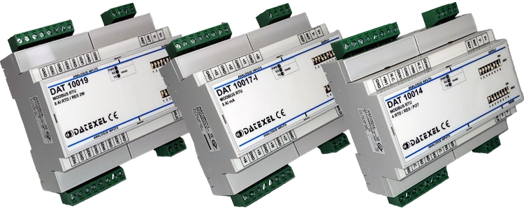
16 Digital Inputs on Modbus RTU.
DAT10148


The DAT10148 Modbus RTU Module is a digital input device with 16 isolated inputs designed for integration into Modbus RTU networks. It allows seamless acquisition of digital signals such as pushbuttons, limit switches, or sensor contacts for PLCs, SCADA, and other Modbus master systems.
The 16 digital inputs detect ON states between 10 and 30 VDC and OFF states below 3 VDC, with a fast sampling time of 5 ms. The module provides three-way galvanic isolation between inputs, outputs, and power supply, ensuring safe and reliable operation in harsh industrial environments.
| INPUT | OUTPUT | POWER SUPPLY |
|---|---|---|
| Modbus RTU, Modbus ASCII. | Modbus RTU, Modbus ASCII | Power Supply Voltage 10-30Vdc |
| 16 Digital inputs. | Reverse polarity protection 60Vdc | |
| CURRENT CONSUMPTION | CONFIGURATION | ISOLATION |
| Between 30 and 110 mA | PC Programmable | Between Input/Comms/Power Supply 2000Vac. |
| DIP Switches | ||
| EMC | HOUSING | TEMPERATURE |
| For Industrial environments | Material self-extinguishing | Operating Temperature 14°F +140°F -10°C +60°C |
| Immunity EN 61000-6-2 | Dimensions W x H x T | Storage Temperature -40°F +185°F-40°C +85°C |
| Emission EN 6100-6-4 | 4" x 4 3/4" x 3/4" | Humidity (non condensing) 0-90% |
| 100 x 120x x 22.5 mm | ||
| Weight 6 oz 160 g |
| Input: | |
| Channels | 16 Channels |
| Voltage | 0-3 V Off 10-30 V on |
| Communication: | |
| Modbus | Modbus RTU, Modbus ASCII . |
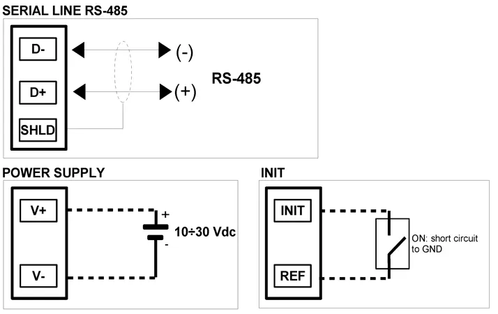
| Power Supply: | 10 - 30 Vdc. Reverse polarity protection 60 Vdc. |
| Current Consumption: | 30 mA to 45 mA. |
| Temperature rating: | Operative Temperature 14°F +140°F -10°C +60°C Storage Temperature - 40°F +185°F - 40°C +85°C. |
| Humidity: | (not condensing) 0-90%. |
| Housing: | Material self-extinguishing. |
| Dimensions: | W x H x T 4 3/4 x 4 x 7/8 inch, 120 x 100 x 22,5mm. |
| Weight: | 7 oz 200 g. |
| EMC. | For industrial environments. |
| Immunity: | EN 61000-6-2. |
| Emission: | EN 61000-6-4. |
| Isolation: | Between Modbus Master, Input, Power supply 1500Vac, 50Hz, 1 Minute. |
| Configuration: | PC Configurable, DIP Switches. |
| Power Supply (18-30Vdc). | Positive J Negative I. |
| RS 485 Slave | Positive (D+)B Negative (D-) A GND C |
| Init | Pin D Init Gnd C |

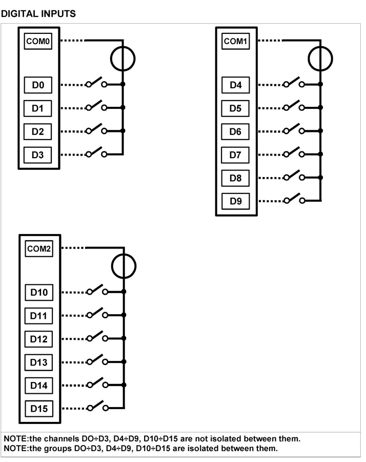
| Digital Input 0 | Commom COM0 Input D0 |
| Digital Input 1 | Commom COM0 Input D1 |
| Digital Input 2 | Commom COM0 Input D2 |
| Digital Input 3 | Commom COM0 Input D3 |
| Digital Input 4 | Commom COM1 Input D4 |
| Digital Input 5 | Commom COM1 Input D5 |
| Digital Input 6 | Commom COM1 Input D6 |
| Digital Input 7 | Commom COM1 Input D7 |
| Digital Input 8 | Commom COM1 Input D8 |
| Digital Input 9 | Commom COM1 Input D9 |
| Digital Input 10 | Commom COM2 Input D10 |
| Digital Input 11 | Commom COM2 Input D11 |
| Digital Input 12 | Commom COM2 Input D12 |
| Digital Input 13 | Commom COM2 Input D13 |
| Digital Input 14 | Commom COM2 Input D14 |
| Digital Input 15 | Commom COM2 Input D15 |
