Din Rail Thermocouple Converter
DAT2145


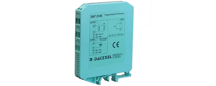
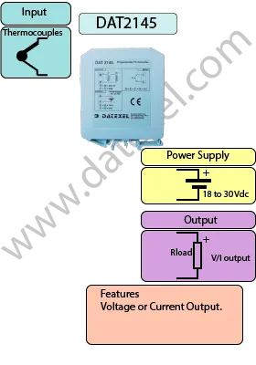
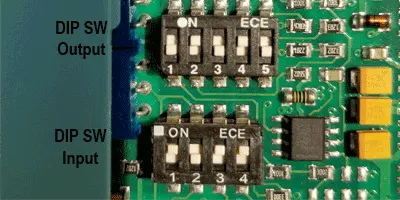
The DAT2145 Thermocouple Converter is a DIN rail mount temperature signal converter that supports a wide range of thermocouple types. It features DIP switch configuration for coarse range and zero, with top-mounted potentiometers for fine-tuning. Unlike the DAT2045, the DAT2145 provides multiple output formats including 4-20 mA, 0-20 mA, and 0-10 V — all voltage-linear.
With an accuracy of 0.1% full scale and a thermal drift below 0.02%/°F, the DAT2145 is a precise and flexible solution for converting thermocouple signals. It includes internal cold junction compensation for improved measurement reliability.
The device is housed in a compact 12.5 mm DIN rail enclosure compliant with EN-50022 and EN-50035 mounting standards and meets EMC requirements (89/336/CEE). Ideal for process control, building automation, and PLC interface applications where multiple output options are required.
| INPUT | OUTPUT | POWER SUPPLY |
|---|---|---|
| Thermocouple. | Current 4-20mA . | Power Supply Voltage 10-30Vdc |
| Volt 0-10V | Reverse polarity protection 60Vdc | |
| CURRENT CONSUMPTION | CONFIGURATION | ISOLATION |
| 40 mA | DIP Switch Programmable | None |
| Span and Zero Adjustable pots | ||
| EMC | HOUSING | TEMPERATURE |
| For Industrial environments | Material self-extinguishing | Operating Temperature -4°F +158°F -20°C +70°C |
| Immunity EN 61000-6-2 | Dimensions W x H x T 3 1/2" x 4 1/2" x 1/2 " | Storage Temperature -40°F +185°F-40°C +85°C |
| Emission EN 6100-6-4 | 90 x 112x x 12.5 mm | Humidity (non condensing) 0-90% |
| Weight 3 oz 90 g |
The DAT2145 is an excellent solution for precise thermocouple signal conversion in industrial environments, offering reliable and stable performance.
| Input type: | Min | Max | Min. span |
| K Type Thermocouple | -58℉ | 2500℉ | 210℉ |
| 50℃ | 1370℃ | 100℃ | |
| J Type Thermocouple | -58℉ | 1650℉ | 210℉ |
| 50℃ | 900℃ | 100℃ | |
| R Type Thermocouple | -58℉ | 3200℉ | 1290℉ |
| 50℃ | 1760℃ | 800℃ | |
| S Type Thermocouple | -58℉ | 3200℉ | 1290℉ |
| 50℃ | 1760℃ | 800℃ | |
| T Type Thermocouple | -58℉ | 840℉ | 210℉ |
| 50℃ | 450℃ | 100℃ | |
| Input impedance | <=10MΩ | ||
| Line resistance influence | 0.2 uV/&ohm |
| Power supply voltage | 10 .. 30 Vdc |
| Current Consumption | Current output 40 mA |
| Voltage output 10 mA |
| Signal type | 4-20 mA |
| 0-20 mA | |
| 0-10 Volts | |
| Burnout condition | High >20 mA or >10 Volts |
| Max output signal | 30 mA or 18 Volts |
| Load resistance | Current output < 500Ω |
| Voltage output > 5 KΩ | |
| Response time | from 10 to 90% 500 ms |
| Warm up time | 3 minutes |
| Calibration error | > of ±0.1% f.s. or ±0.1 ℉ ±0.2 ℃ |
| Linearity error | ±0.05% f.s. |
| Cold junction Compensation | ±0.5% f.s. |
| Thermal drift | 0.01% f.s./℉ for 500℉ |
| 0.02% f.s./℃ for 500℃ |
| Operative temperature | -4℉ to 158℉ |
| -20℃ to 70℃ | |
| Storage temperature | -40℉ to 185℉ |
| -40℃ to 85℃ | |
| Humidity (not condensed) | 0 to 90 % |
| Maximum Altitude | 6500ft 2000m |
| Installation | indoor |
| Category of installation | II |
| Weight | 3 Oz |
| 90 g. | |
| Material | Self-extinguish plastic |
| IP Rating | IP20 |
| Wiring size | AWG 14-18 |
| 0.8÷2.1 mm² | |
| Screw torque | 0.8 N m |
| Mounting | DIN rail standard EN-50022 and EN-50035 |
| Dimensions | H 3.5" L 4.4" T 0.5" |
| H 90 mm L 112 mm T 12.5 mm | |
| EMC | For industrial environments |
| Immunity | EN 61000-6-2 |
| Emission | EN 61000-6-4 |
| Input | |
| Thermocouple | Terminals L and I |
| Power supply | Positive +V R Negative -V P |
| Output Current | Positive +V N Negative -V P |
| Output Voltage | Positive +V N Negative -V P |
| No Connection | G,H,E,and F |


| Output Signal Span | SW1 | SW2 | SW3 | SW4 | SW5 | 4 to 20 mA | On | Off | On | Off | On |
| 0 to 20 mA | On | On | On | Off | Off |
| 0 to 10 Volts | Off | On | Off | On | Off |
K type Thermocouple
| Span | SW1 | SW2 | SW3 |
| 210 to 300℉ 100'C to 150℃ | On | On | Off |
| 300 to 940℉ 150'C to 505℃ | On | On | Off |
| 940 to 2500℉ 505'C to 1370℃ | On | On | Off |
| Zero | SW4 | ||
| -58 to 14℉ -50 to -10℃ | Off | ||
| 14 to 122℉ -10 to 50℃ | On |
J type Thermocouple
| Span | SW1 | SW2 | SW3 |
| 210 to 240℉ 100'C to 115℃ | Off | On | Off |
| 240 to 390℉ 115'C to 200℃ | Off | On | On |
| 390 to 1110℉ 200'C to 600℃ | Off | On | On |
| 11100 to 1650℉ 600'C to 900℃ | Off | Off | On |
| Zero | SW4 | ||
| -58 to 14℉ -50 to -10℃ | Off | ||
| 14 to 122℉ -10 to 50℃ | On |
R type Thermocouple
| Span | SW1 | SW2 | SW3 | SW4 |
| 1290 to 1470℉ 700'C to 800℃ | Off | On | Off | On |
| 1470 to 3200℉ 800'C to 1760℃ | Off | On | On | On |
S type Thermocouple
| Span | SW1 | SW2 | SW3 | SW4 |
| 1290 to 1470℉ 700'C to 800℃ | Off | On | Off | On |
| 1470 to 3200℉ 800'C to 1760℃ | Off | On | On | On |
T type Thermocouple
| Span | SW1 | SW2 | SW3 | SW4 |
| 210 to 300℉ 100'C to 150℃ | Off | On | Off | On |
| 300 to 840℉ 150'C to 450℃ | Off | On | On | On |