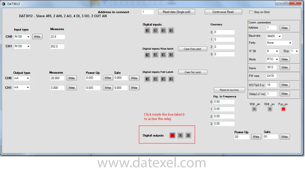
ModBus RTU IO Module
DAT3012
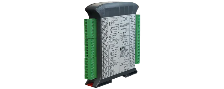

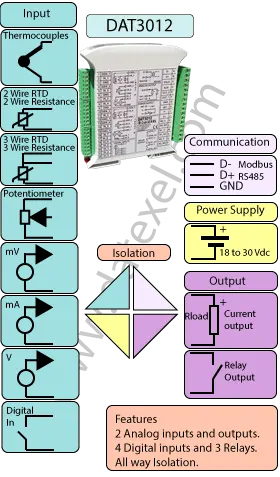
The DAT3012 Modbus RTU I/O Module is a flexible input-output device that combines universal analog inputs, analog outputs, digital inputs, and relay outputs with an isolated RS-485 Modbus RTU slave interface. It can acquire signals from voltage, thermocouples, RTDs, resistance, potentiometers, and current and retransmit them as isolated analog outputs while publishing data over a Modbus network.
I/O summary: 2 universal analog inputs, 2 isolated analog outputs (4–20 mA / 0–20 mA), 4 digital inputs (up to 3 kHz), and 3 SPST relay outputs rated up to 2 A.
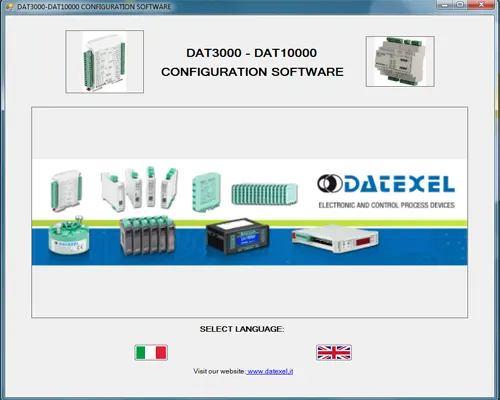
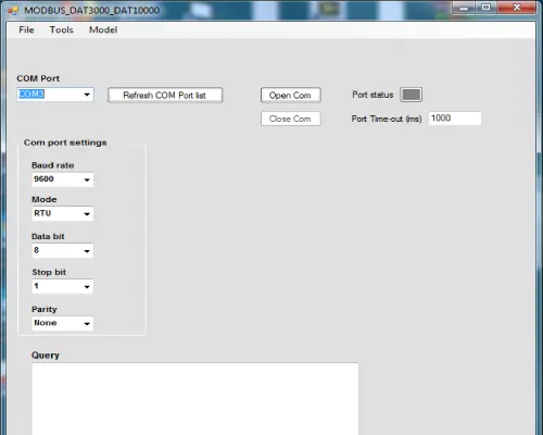
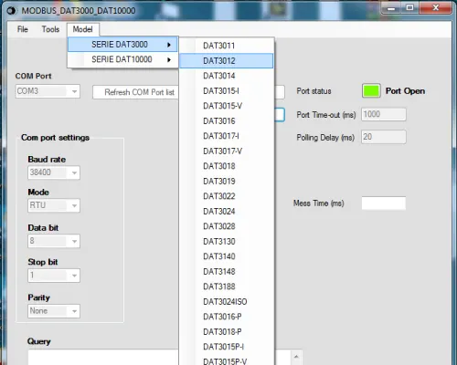
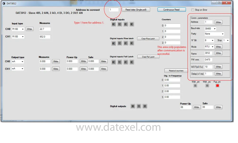
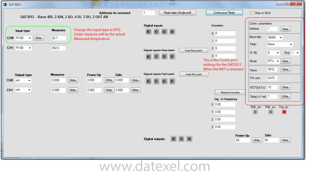
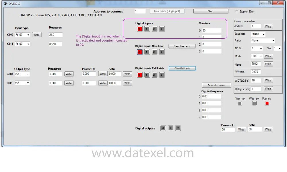
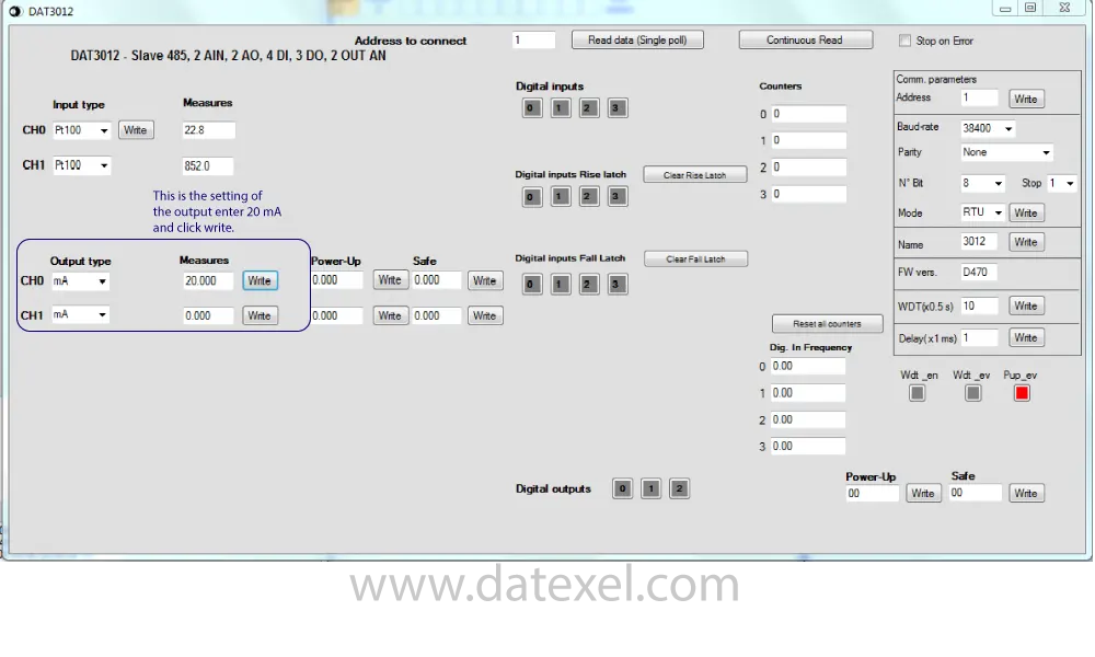
The analog input type is software-selectable and can be configured remotely via Modbus and the free DAT3000-10000 software. This makes the DAT3012 an ideal choice as an isolated Modbus analog input card, an isolated 4–20 mA output module, a digital input counter, or a relay output driver.
Complete all-way galvanic isolation is provided between inputs, outputs, power supply, and RS-485 port, ensuring safe and reliable operation even in harsh industrial environments.
| INPUT | OUTPUT | POWER SUPPLY |
|---|---|---|
| mV, Volts, mA, 4 Digital Inputs. | 2 X Current 4-20mA. | Power Supply Voltage 18-30Vdc |
| RTD, Resistance, Potentiometer,Thermocouples. | 3 SPST Relays. | Reverse polarity protection 60Vdc |
| CURRENT CONSUMPTION | CONFIGURATION | ISOLATION |
| Between 30 and 100 mA | PC Programmable | Between Input/Output/RS485/Power Supply 1500Vac. |
| EMC | HOUSING | TEMPERATURE |
| For Industrial environments | Material self-extinguishing | Operating Temperature 14°F +140°F -10°C +60°C |
| Immunity EN 61000-6-2 | Dimensions W x H x T 4" x 4 3/4" x 3/4" | Storage Temperature -40°F +185°F-40°C +85°C |
| Emission EN 6100-6-4 | 100 x 120x x 22.5 mm | UL Operative Temperature 14°F +104°F -10°C +40°C |
| Weight 3 oz 90 g |
| Input type: | Min | Max |
| Current | ||
| 20 mA | -20 mA | 20 mA |
| Voltage | ||
| 100 mV | -100 mV | 100 mV |
| 10 V | -10 V | 10 V |
| Thermocouple | ||
| J Type Thermocouple | -346℉ | 2192℉ |
| -210℃ | 1200℃ | |
| K Type Thermocouple | -346℉ | 2498℉ |
| -210℃ | 1370℃ | |
| R Type Thermocouple | -58℉ | 3200℉ |
| -50℃ | 1760℃ | |
| S Type Thermocouple | -58℉ | 3200℉ |
| -50℃ | 1760℃ | |
| B Type Thermocouple | 752℉ | 3317℉ |
| 400℃ | 1825℃ | |
| E Type Thermocouple | -346℉ | 1832℉ |
| -210℃ | 1000℃ | |
| T Type Thermocouple | -346℉ | 752℉ |
| -210℃ | 400℃ | |
| N Type Thermocouple | -346℉ | 2372℉ |
| -210℃ | 1300℃ | |
| RTD 2, 3 Wire | ||
| Pt 100 | -328℉ | 1562℉ |
| -200℃ | 850℃ | |
| Pt 1000 | -328℉ | 392℉ |
| -200℃ | 200℃ | |
| Ni 100 | -76℉ | 356℉ |
| -60℃ | 180℃ | |
| Ni 1000 | -76℉ | 302℉ |
| -60℃ | 150℃ | |
| Resistance 2,3 Wires | ||
| Low | 0 Ω | 100 Ω |
| High | 0 Ω | 2000 Ω |
| Accuracy | ||
| mV, Volt, mA, Pot, RTD, Resistance | ±0.05% f.s. | |
| Thermocouple | > of ±0.05% f.s. or 5uV | |
| Linearity. | ||
| mV, Volt, mA | ±0.05% f.s. | |
| Pot, RTD, Resistance | ±0.1% f.s. | |
| Thermocouple | ±0.2% f.s. | |
| Excitation Current. | RTD, Res, Pot. | Typical 0.7 mA |
| Line resistance influence | ||
| RTD, Res 3 wires | 0.05 f.s.%/Ω | |
| mV, T/C | 0.8 uV/Ω | |
| CJC error | ± 1.8 ℉ | ± 1 ℃ |
| Input Impedance | ||
| mV, Thermocouple | 10 MΩ | |
| mA | 22 Ω | |
| Thermal Drift | ||
| Inputs Full Scale | ±0.01% f.s./℉ | ±0.01% f.s./℃ |
| Thermal Drift CJC | ||
| Full Scale | ±0.02% f.s./℉ | ±0.02% f.s./℃ |
| Number of Channels | 4 Channels |
| Pulse Counters 32 bit | 4 up to 3 kHz |
| Input Voltage | Off State 0-3V |
| On State 10-30V | |
| Input Impedance | 4.7 KΩ |
| Signal type | Min | Max |
| 0 mA | 20 mA | |
| Accuracy | ±0.05% f.s. | |
| Linearity | ±0.05% f.s. | |
| Thermal Drift | ±0.01% f.s. | |
| Load resistance | < 500Ω | |
| Auxiliary Voltage | 12 Volts @ 20 mA | |
| Sample Time | from 10 to 90% 500 ms | |
| Warm up time | 3 minutes | |
| Digital Output | ||
| Number of outputs | 3 | |
| Max Switching power | 2 A @ 250 Vac | 2 A @ 30 Vdc |
| Minimum Load | 5 Vdc, 10mA | |
| Dielectric Strength Between Contacts |
1000 Vac | 50 Hz 1 Min |
| Dielectric Strength Between Coil and Contacts |
1000 Vac | 50 Hz 1 Min |
| Baud Rate | Up to 115.2 Kbps | |
| Maximum Distance | 4000 ft | 1.2 Km |
| Power supply voltage | 18 .. 30 Vdc |
| Reverse polarity protection | 60 Vdc max |
| Current Consumption | 100 mA |
| Power Supply RS485 Analog input Analog output Digital Input Relays |
1500Vac 50Hz, 1 Min |
| Operative temperature | 14℉ to 140℉ |
| -10℃ to 60℃ | |
| UL Operative temperature | 14℉ to 104℉ |
| -10℃ to 40℃ | |
| Storage temperature | -40℉ to 185℉ |
| -40℃ to 85℃ | |
| Humidity (not condensed) | 0 to 90 % |
| Maximum Altitude | 6500ft 2000m |
| Installation | Indoor |
| Category of installation | II |
| Pollution Degree | 2 |
| Weight | 6 Oz |
| 150 g. | |
| Material | Self-extinguish plastic |
| IP Rating | IP20 |
| Wiring size | AWG 14-18 |
| 0.8÷2.1 mm² | |
| Screw torque | 0.8 N m |
| Mounting | DIN rail standard EN-50022 and EN-50035 |
| Dimensions | H x" L x" T x" |
| H 100 mm L 120 mm T 22.5 mm | |
| EMC | For industrial environments |
| Immunity | EN 61000-6-2 |
| Emission | EN 61000-6-4 |


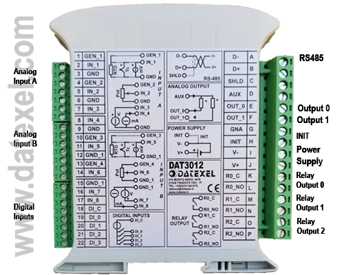
| Input. | Channel A | Channel B1 |
| RTD 3 Wire | 3 and 2 Compensation 1 | 13 and 11 Compensation 10 |
| Potentiometer | 6 and 4 Wiper 5 | 15 and 13 Wiper 14 |
| mV | Positive 2 Negative 3 | Positive 11 Negative 12 |
| Thermocouple | Positive 2 Negative 3 | Positive 11 Negative 12 |
| Volts | Positive 7 Negative 9 | Positive 16 Negative 15 |
| mA | Positive 8 Negative 9 | Positive 17 Negative 15 |
| Common | 3, 6, 9 | 12, 13 |

| Common | 18 |
| DI 0 | Terminal 19 |
| DI 1 | Terminal 20 |
| DI 2 | Terminal 21 |
| DI 3 | Terminal 22 |
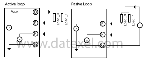
| Active Loop | Passive Loop | |
| Auxiliary Voltage Output | Terminal D | |
| Terminal E | Load 0 Return | Load 0 Return |
| Terminal F | Load 1 Return | Load 1 Return |
| Terminal G | No Connection | Ground |

| Relay 0 | Terminal K | Terminal L |
| Relay 1 | Terminal M | Terminal N |
| Relay 2 | Terminal O | Terminal P |

| Power Supply | ||
| 18 -30 Vdc | Terminal J Positive | Terminal I Ground |
| RS-485 | ||
| Terminal A D- | Terminal B D+ | Terminal C Ground |
| Init | ||
| Terminal H Init | Terminal B Ground |

| LED | Color | State | Description |
| PWR | Green | On OFF Blink |
Power On Power Off Watch-Dog Alarm |
| STS | Yellow | Off | Correct operation |
| RX | Red | Blink Off |
Receiving Data No Data Receiving |
| TX | Red | Blink Off |
Send Data Not Send Data |
| I(n) | Red | On Off |
Digital Input "n" On Digital Input "n" Off |
| R(n) | Red | On Off |
Digital Output "n" On Digital Output "n" Off |
The ModBus RTU IO module DAT3012 is suitable for fitting on to an EN-50022 top hat DIN rail in the vertical position. For optimum operation follow these instructions: Install the DAT3012 side by side. However, it may be necessary to separate them by at least 5 mm in the following case: Avoid temperature exceeding 45°C. Make sure that sufficient air flow is provided for the DAT3012 ventilation slits. Avoid mounting above appliances generating heat. Fit the DAT3012 in the lower part of the panel. Avoid high vibration. Don't route conductors near power signal cables such as motors, induction ovens, inverters, also use shielded cable for connecting signals.
