RS485 Input Module
DAT3148-12


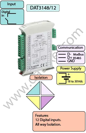
The DAT3148/12 is a Modbus RTU/ASCII digital input module capable of acquiring up to 12 digital inputs. The data are transmitted over the RS-485 network, enabling easy integration into PLCs, SCADA systems, and other Modbus master devices.
The module ensures high accuracy and stable performance over time and across temperature variations. For plant safety, it provides two Watchdog timer alarms. Galvanic isolation between circuit parts eliminates ground-loop effects, allowing reliable operation even in harsh industrial conditions.
The DAT3148/12 complies with UL 61010-1 for the US market and CSA C22.2 No 61010-1 for the Canadian market. It is housed in a rugged, self-extinguishing plastic container with a slim profile of 17.5 mm, allowing high-density mounting on EN-50022 standard DIN rails.
The DAT3148/12 communicates via the Modbus RTU/ASCII protocol, a widely used standard in field-bus systems. This ensures compatibility with most PLCs, SCADA systems, and Modbus-based applications. Detailed protocol instructions are available in the device User Guide.
| INPUT | OUTPUT | POWER SUPPLY |
|---|---|---|
| 18 Digital Inputs | Modbus RTU/ASCII | Power Supply Voltage 18-30Vdc |
| Modbus RTU/ASCII | Reverse polarity protection 60Vdc | |
| CURRENT CONSUMPTION | CONFIGURATION | ISOLATION |
| Between 60 and 115 mA | PC Programmable | Between Input/Comms/Power Supply 2000Vac. |
| EMC | HOUSING | TEMPERATURE |
| For Industrial environments | Material self-extinguishing | Operating Temperature 14°F +140°F -10°C +60°C |
| Immunity EN 61000-6-2 | Dimensions W x H x T 4" x 4 3/4" x 3/4" | Storage Temperature -40°F +185°F-40°C +85°C |
| Emission EN 6100-6-4 | 100 x 120x x 22.5 mm | Humidity (non condensing) 0-90% |
| Weight 3 oz 90 g |
| Digital Input | 12 Channels, Off State 0-3 V, On State 10-30V. |
| States | Off State 0-3 V, On State 10-30V. |
| Output | 8 Channels. |
| States | 30 Vdc 600mA per channel 3 A per Module |
| Communication: | RS485 Modbus. |
| Power Supply: | 18 - 30 Vdc. Reverse polarity protection 60 Vdc. |
| Current Consumption: | 30 mA. |
| Temperature rating: | Operative Temperature -4°F +140°F -20°C +60°C Storage Temperature -40°F +185°F -40°C +85°C. |
| Humidity: | (not condensing) 0-90%. |
| Housing: | Material self-extinguishing. |
| Dimensions: | W x L x H 3 3/4X 3 1/2 X 1 7/8 inch, 90 x 74 x 48mm. |
| Weight: | 7 oz 200 g. |
| EMC. | For industrial environments. |
| Immunity: | EN 61000-6-2. |
| Emission: | EN 61000-6-4. |
| Isolation: | Between Modbus Master, Slave/Power supply 1500Vac, 50Hz, 1 Minute. |
| Configuration: | PC Configurable. |
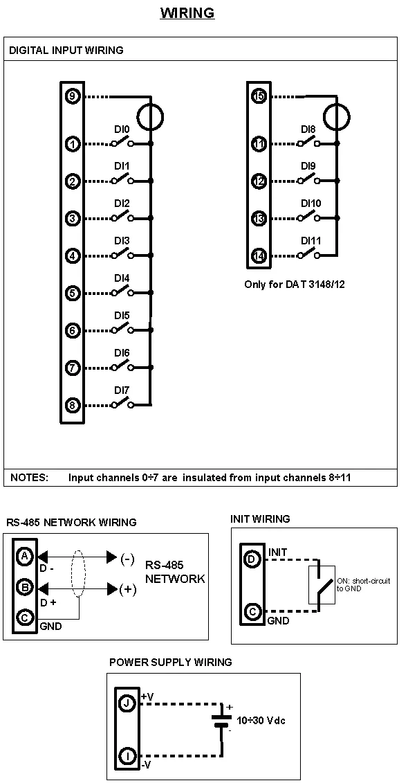
| Input | |
| Digital Input 0 | Common 9 Input 1 |
| Digital Input 1 | Common 9 Input 2 |
| Digital Input 2 | Common 9 Input 3 |
| Digital Input 3 | Common 9 Input 4 |
| Digital Input 4 | Common 9 Input 5 |
| Digital Input 5 | Common 9 Input 6 |
| Digital Input 6 | Common 9 Input 7 |
| Digital Input 7 | Common 9 Input 8 |
| Digital Input 8 | Common 15 Input 11 |
| Digital Input 9 | Common 15 Input 12 |
| Digital Input 10 | Common 15 Input 13 |
| Digital Input 11 | Common 15 Input 14 |
| Power Supply (18-30Vdc). | Positive J Negative I. |
| RS 485 Slave | Positive (D+)B Negative (D-) A GND C |
| Init | Pin D Init Gnd C |
