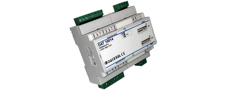
4 channel RTD input to Modbus RTU DAT10014
DAT10014


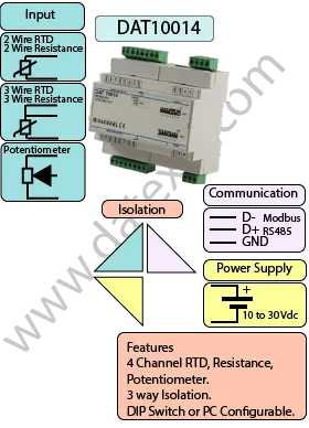
The DAT10014 Modbus RTU Converter is a 4-channel slave device designed for acquiring signals from RTDs, potentiometers, and resistance sensors and converting them into Modbus RTU data. This makes it an efficient solution for integrating multiple sensors into SCADA systems, PLCs, and other Modbus-compatible equipment.
Configuration is simple via front-panel DIP switches, which allow the user to set the Modbus address, baud rate, parity, and communication mode (RTU or ASCII). For more advanced setup, the DAT10014 can also be configured using the free DAT3000–10000 configuration software, providing fast and flexible programming options.
Each of the four channels can be individually managed, providing flexible data acquisition in a single compact unit. The device provides 1500 Vac galvanic isolation between input, output, and power supply, ensuring safe and reliable operation even in electrically noisy environments. It operates from a 10–30 VDC power supply, making it suitable for a wide range of industrial applications.
| INPUT | OUTPUT | POWER SUPPLY |
|---|---|---|
| RTD, Resistance, Potentiometer. | Modbus RTU RS485 | Power Supply Voltage 10-30Vdc |
| Reverse polarity protection 60Vdc | ||
| CURRENT CONSUMPTION | CONFIGURATION | ISOLATION |
| Between 30 and 45 mA | PC Programmable | Between Input/Comms/Power Supply 1500Vac. |
| DIP Switch | ||
| EMC | HOUSING | TEMPERATURE |
| For Industrial environments | Material self-extinguishing | Operating Temperature 14°F +140°F -10°C +60°C |
| Immunity EN 61000-6-2 | Dimensions W x H x T 4.1/4" x 4 1/2" x 2 1/4" | Storage Temperature -40°F +185°F-40°C +85°C |
| Emission EN 6100-6-4 | 106 x 112x x 57 mm | Humidity (non condensing) 0-90% |
| Weight 7 oz 200 g |
| Input: | |
| RTD | 4 Channels Pt100, Pt1000, Ni100, Ni1000 |
| Resistance | 0-500 Ohm, 0-2000 Ohm. |
| Potentiometer | 500 Ohm, 2000 Ohms. |
| Communication: | |
| RS485: | Modbus RTU, Modbus ASCII. |
| Power Supply: | 10 - 30 Vdc. Reverse polarity protection 60 Vdc. |
| Current Consumption: | 30 mA to 45 mA. |
| Temperature rating: | Operative Temperature 14°F +140°F, - 10°C +60°C Storage Temperature - 40°F +185°F, - 40°C +85°C. |
| Humidity: | (not condensing) 0-90%. |
| Housing: | Material self-extinguishing. |
| Dimensions: | W x L x H 4 1/4X 4 1/2 X 2 1/4 inch, 106 x 112 x 57mm. |
| Weight: | 7 oz 200 g. |
| EMC. | For industrial environments. |
| Immunity: | EN 61000-6-2. |
| Emission: | EN 61000-6-4. |
| Isolation: | Between Modbus Master, Input, Power supply 1500Vac, 50Hz, 1 Minute. |
| Configuration: | PC Configurable, DIP Switch. |
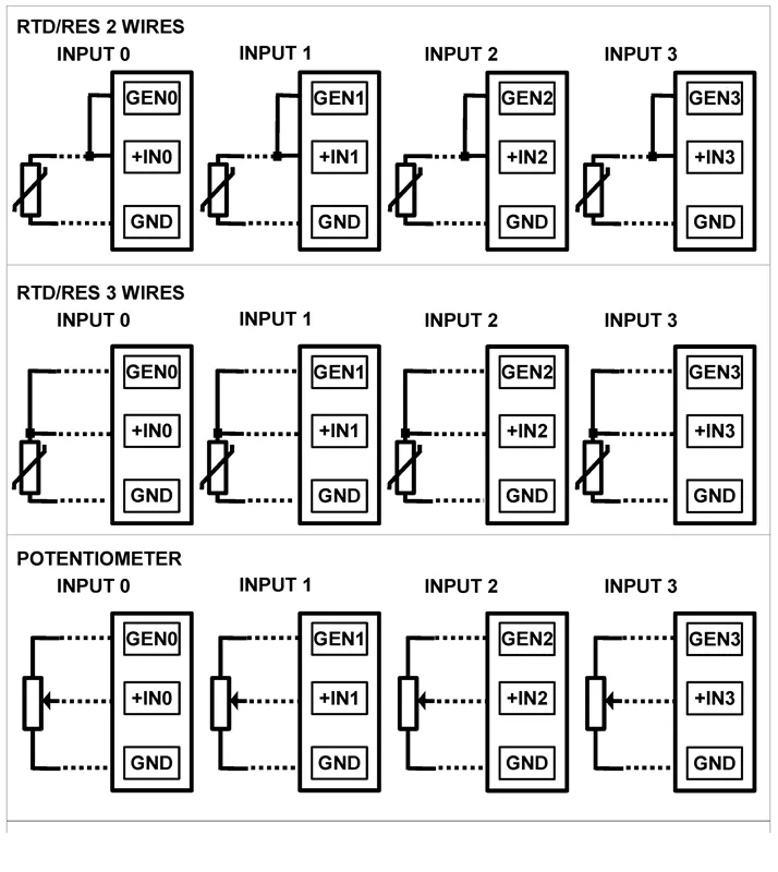
| 2 Wire RTD and Resistance Input 0 | Sensor on GND and +IN0 and Compensation on GEN0 |
| 2 Wire RTD and Resistance Input 1 | Sensor on GND and +IN1 and Compensation on GEN1 |
| 2 Wire RTD and Resistance Input 2 | Sensor on GND and +IN2 and Compensation on GEN2 |
| 2 Wire RTD and Resistance Input 3 | Sensor on GND and +IN3 and Compensation on GEN3 |
| 3 Wire RTD and Resistance Input 0 | Sensor on GND and +IN0 and Compensation on GEN0 |
| 3 Wire RTD and Resistance Input 1 | Sensor on GND and +IN1 and Compensation on GEN1 |
| 3 Wire RTD and Resistance Input 2 | Sensor on GND and +IN2 and Compensation on GEN2 |
| 3 Wire RTD and Resistance Input 3 | Sensor on GND and +IN3 and Compensation on GEN3 |
| Potentiometer Input 0 | Sensor on GND and +IN0 and Wiper on GEN0 |
| Potentiometer Input 1 | Sensor on GND and +IN1 and Wiper on GEN1 |
| Potentiometer Input 2 | Sensor on GND and +IN2 and Wiper on GEN2 |
| Potentiometer Input 3 | Sensor on GND and +IN3 and Wiper on GEN3 |

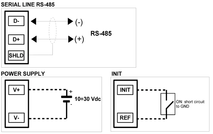
| Power Supply (18-30Vdc). | Positive V+ Negative V-. |
| RS 485 Slave | Positive (D+)B Negative (D-) A GND C |
| Init | Pin Init Ref |
