Modbus Remote Display.

DAT9550

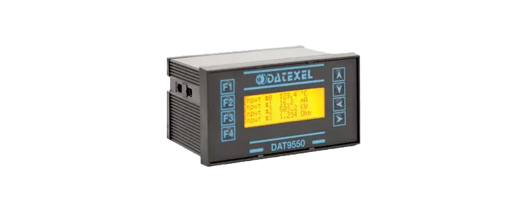
Modbus Remote Display DAT9550
Modbus Remote display.
• Modbus Remote Display.
• RS485 and RS232 Communication.
• Graphical Display.
• 132 x 32 pixels.
• Modbus Master.
• Modbus Slave.
• Galvanically Isolated.
General Description

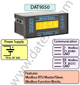
The Modbus Remote Display DAT9550 is a graphical display designed for panel mounting and is able to communicate with Modbus RTU protocol. The DAT9550 has an RS485 Modbus Master port and a Modbus Slave port which can accept either RS485 or RS232.
It can be used to monitor or control any Modbus RTU network. It can also be used to display data coming from the DATEXEL range of DAT9000 Intelligent units or the DAT3000 series of analog and Digital I0 devices. It can also be used to display data coming from PLC's, PC or any other Modbus device. As the DAT9550 is a Modbus master it can be connected to any of the Datexel slave IO devices and indicate their measured variable. You can also connect the analog or digital output and have a complete control system.
Simple applications like measuring 8 thermocouples and having high or low-level temperature alarms can be simply implemented.

INPUT OUTPUT POWER SUPPLY
Modbus Master/Slave RS232 RS485 Power Supply Voltage 10-30Vdc
Reverse polarity protection 60Vdc
CURRENT CONSUMPTION CONFIGURATION ISOLATION
Between 60 and 115 mA PC Programmable Between Input/Comms/Power Supply 1500Vac.
EMC HOUSING TEMPERATURE
For Industrial environments Material self-extinguishing Operating Temperature 14°F +140°F -10°C +60°C
Immunity EN 61000-6-2 Dimensions W x H x T 3 3/4" x 1 7/ " x 2 1/2" Storage Temperature -40°F +185°F-40°C +85°C
Emission EN 6100-6-4 96 x 48 x 64 mm Humidity (non condensing) 0-90%
Weight 7 oz 200 g

Specifications
Digital Display 132 X 32 Pixels.
Communication:  
RS485: Port 1 Modbus RTU Master, Port 0 Modbus RTU Slave.
RS232: Serial Slave Port.
Power Supply: Voltage 10 - 30 Vdc. Reverse polarity protection 60 Vdc.
Current Consumption: 80 mA max.
Temperature rating: Operative Temperature -4°F +140°F -20°C +60°C
Storage Temperature -40°F +185°F -40°C +85°C.
Humidity: (none condensing) 0-90%.
Housing: Material self-extinguishing.
Dimensions: W x L x H 4 x 4 3/4 x 1inch, 100 x 120 x 22.5mm.
Weight: 7 oz 200 g.
EMC. For industrial environments.
Immunity: EN 61000-6-2.
Emission: EN 61000-6-4.
Isolation: 1500Vac, 50Hz, 1 Minute.
Configuration: PC Configurable, Front Panel Switches.
Drawings

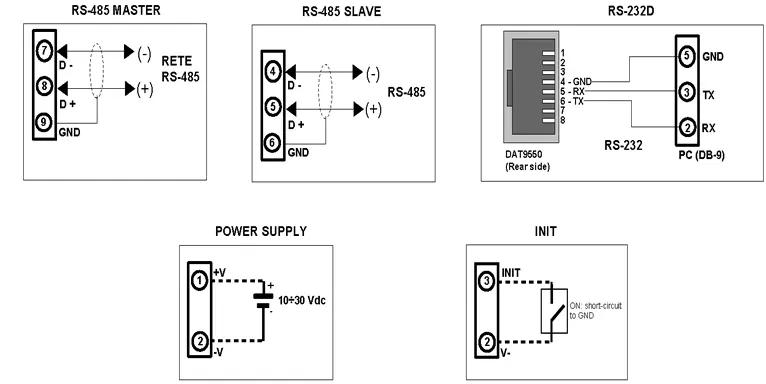
DAT9000DLIO Wiring Diagram

Power Supply (18-30Vdc). Positive 1 Negative 2.  
RS 485 Master Positive (D+)8 Negative (D-) 7 GND 9  
RS 485 Slave Positive (D+)5 Negative (D-) 4 GND 6  
  DAT9550 Rear PC DB9
RS-232D 4 GND Pin 5
  5 RX Pin 3 TX
  8 TX Pin 2 Rx
Init Pin 3 Init Pin2 V-
Modbus Remote Display wiring Diagram.
Applications
Frequently Asked Questions
Back to General Description
Application Note, Using a Remote Modbus Display and an 8 Channel Thermocouple Modbus Slave.
This application reads the temperature from the registers in a Modbus RTU Slave DAT3018 and displays them on a Remote Modbus Display DAT9550.
Printed Version

Start-up.

  1. The 8 Channel temperature Modbus Slave RTU device is set up to Baud Rate 9600, Parity None and 1 Stop bit.
  2. The Address is 20 and Modbus Display Address is 1.
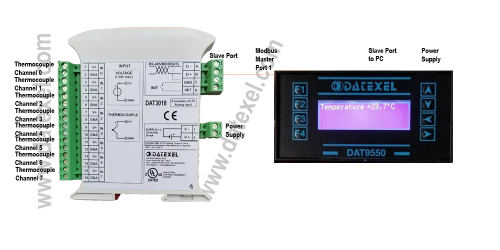
  3. The DAT9550 only has a Modbus RS485 connection. Connect the DAT3018 Slave port to the Master port of the DAT9550. The PC should be connected to the Modbus Slave port.
Using a Remote Modbus Display and a Thermocouple Modbus Slave.

Wiring connections for Modbus Temperature Slave and Remote Modbus Display.

  1. Connect a temperature calibrator to channel 1or short out the input to measure the ambient temperature.
  2. Connect 24 Vdc power supply to the DAT3018 and DAT9550.
  3. Connect the DAT3018 Modbus port to the Modbus Master port on the DAT9550.
  4. Run the Dev9K software from Datexel download page.

Connecting to the Remote Modbus Display.

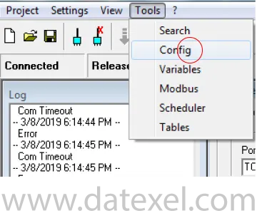
  1. Click on Tools.
  2. From the drop down menu click Search.
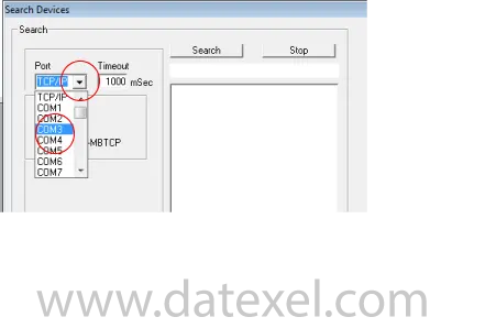
Setting up Remote Modbus Display comm port.

Setting up the DEV 9K Software to talk to the Modbus Slave Port.

  1. Click the port Label and change the port to Com3 (or whatever your com port setting is).
Configuring the Remote Modbus Display communication port.

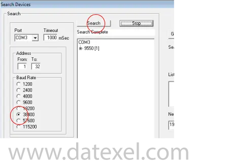
Setting the Baud Rate.

  1. On the drop down menu select the slave port Baud Rate setting. Factory default is 38400. If you have used the INIT it will be 9600.
  2. Click Search.
  3. Com3 should appear then 9550 [1] indicating that it is connected.
  4. The [1] indicates that the DAT9550 is Address 1.
Setting up Modbus Display Baud Rate.

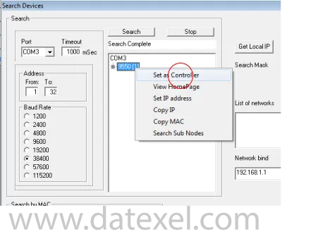
Set the Modbus Display as the Controller.

  1. Right click on the 9550.
  2. Click the Set as Controller label.
  3. You are now able to write the program and load it into the DAT9550 Modbus Display.
Setting up a Modbus Display to act as a Modbus Master.

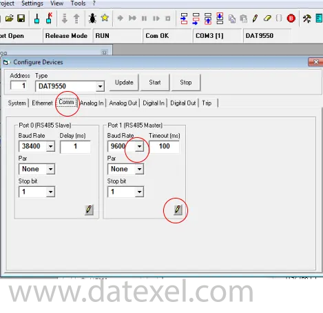
Change the Baud Rate of the DAT9550 Master Port.

As the Baud Rate of the Modbus Thermocouple Slave is 9600 Mbps, the Master port on the DAT9550 has to be changed to communicate with the DAT3018.
  1. Click Tools.
  2. On the drop down menu Click Config.
  3. Click Comm.
  4. Change the Baud Rate to 9600.
  5. Click the pencil to write to the DAT9550.
Setting up the Modbus Display Salve Port.

Start the Program.

As the Baud Rate of the Modbus Thermocouple Slave is 9600 Mbps, the Master port on the DAT9550 has to be changed to communicate with the DAT3018.
  1. Right click on the 9550.
  2. Click the Set as Controller label.
  3. You are now able to write the program and load it into the DAT9550 Modbus Display.
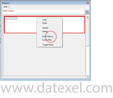
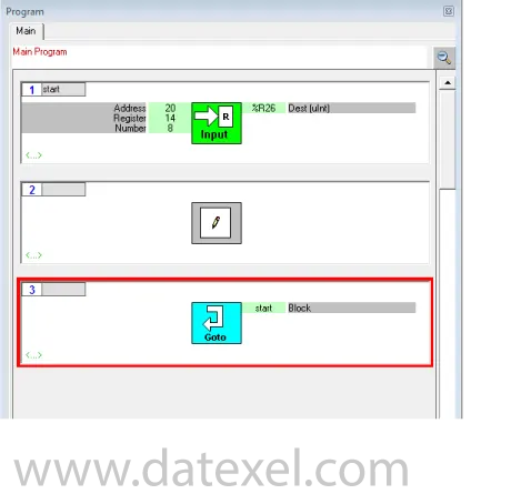
The program is made up with a group of function blocks. More information on these function blocks are available in the DAT9xxx user guide. Importantly the first function block must be labeled start and the last function block must be a goto function block with the command return to start. You can insert a function block anywhere in the program with the Insert Before or Insert After label.
Programming the Modbus Display.

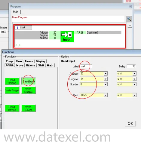
The Read Input Function Block.

  1. Click Project.
  2. Click New from the Drop down menu.
  3. Right click on Function Block 1.
  4. On the drop down menu click Modify.
  5. Click Comm and select Read Input.
  6. Write start in the Label. (Important).
  7. The Address of the Modbus Thermocouple Slave is 20.
  8. The Register where the temperature is stored for channel 0 is 14.
  9. As we are going to read all the 8 Channels write 8 in Number.
  10. The destination register in the DAT9550 is 26 so insert %R26 in Dest.
  11. Click OK.
Read input function block.

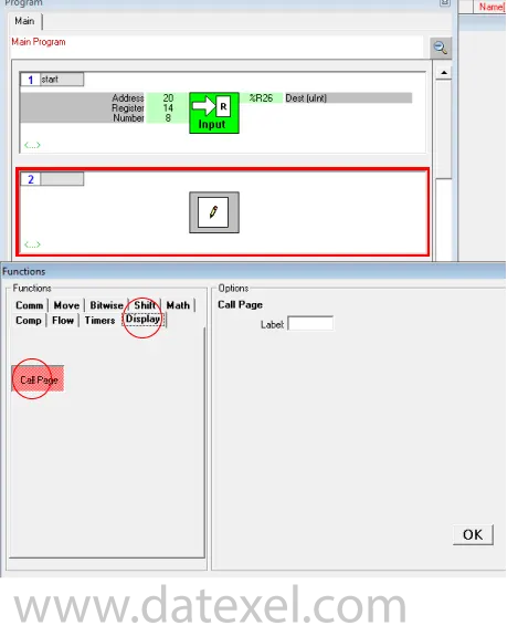
The Display Function Block.

  1. Click Project.
  2. Insert another function block.
  3. Select Display and click Call Page. This refreshes the display whilst the program is running.
Read input function block.

The Goto Function Block.

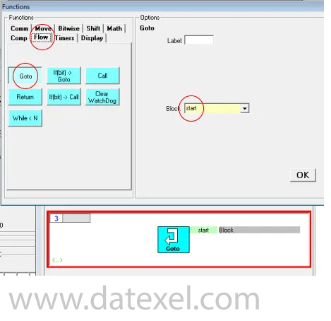
  1. Insert another function block called “Flow”, Click “Goto”. In the Block box write start. Make sure it is the same case and spelling as the Label in the first function block.
  2. This function block returns the project back to the beginning.
Modbus Display Goto Function Block.

Saving the Project.

  1. Click “Project” on the drop down menu Click “Save as” .
  2. Save as Display2019.
It is best at this stage to run the project to check communication with the Thermocouple Modbus Slave.
Modbus Display complete project.

Downloading the Project from the PC to the DAT9550.

  1. Make sure you are still connected to the DAT9550 and set as controller again.
  2. Click the Debug button.
  3. Click the Download button, in the download drop down menu click OK.
  4. The project will now download from the PC to the DAT9550.
  5. Wait until the download has finished and click the Star Button (Set Release Button).
  6. It is very important now to click the Release mode.
  7. Now the program is stored in the DAT9550.
  8. Click the yellow R register button on the register table and check that the reading is in Register 26. Also Register 27 to 33 should have readings.
  9. Adjust the calibrator whilst clicking the R button and watch the temperature change. Please note the temperature is x 10.

The Display now needs to be set up.

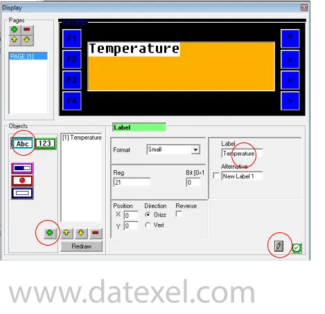
  1. Click “Tools” and open the “Display” page.
  2. Click The Abc Button then the + Button.
  3. This opens the first Label type ”Temperature” under the Label Title.
  4. Click the pencil.
Displaying Temperature on a Remote Modbus Display.

Displaying the Register.

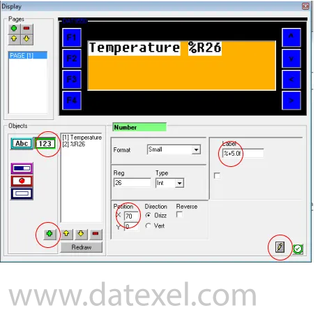
  1. Click the 123 Button and then the +Button.
  2. Under the Reg write in 26 for register 26.
  3. Under Label write %+5.1f. This is for 1 decimal place.
  4. Next to the X position type 70. This moves the indication of Register 26 to 70 pixels to the right on the Horizontal position.
  5. Click the pencil.
Displaying Registers on a Remote Modbus Display.

Positioning the Celsius Label.

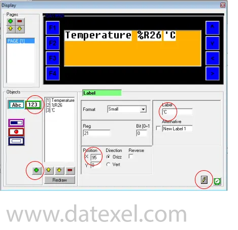
  1. Click The Abc Button then the + Button.
  2. This opens the Label to indicate Celsius.
  3. Type ”’C” under the Label Title.
  4. Next to the X position type 95.
  5. Click the pencil.

Saving the Complete Project.

The project is now complete. Save the project as before. Connect to the DAT9550 and set as Controller and Download the project and set Release.
Displaying Celsius on a Remote Modbus Display.

Run the Project.

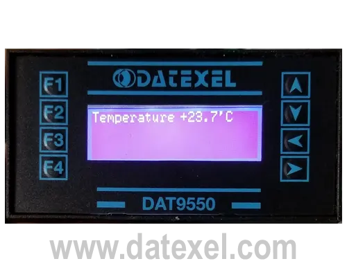
  1. The correct temperature should now be displayed on the DAT9550. Adjust the calibrator to see the correct operation.
  2. If more parameters need to be displayed just add in the Display section.

Saving the Complete Project.

The project is now complete. Save the project as before. Connect to the DAT9550 and set as Controller and Download the project and set Release.
Modbus Display complete project.

Explanation of the Project.

DAT9550 Custom products

What is a DAT 9550 10920?
The DAT9550 10920 was designed in conjunction with the DAT 3011 10920. The DAT3011 measures two Pt100 RTD's and the DAT9550 displays the differential temperature. The DAT3011 10920 provides a 4-20 mA output equal to the differential temperature.
Back to General Description