Modbus RTU Datalogger
DAT9000DL
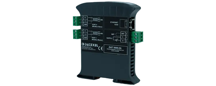

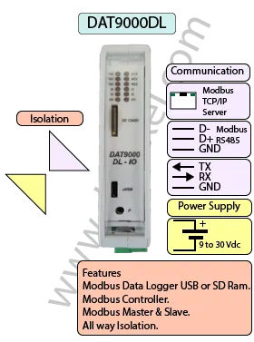
The DAT9000DL Modbus RTU Datalogger is a data acquisition and control unit with an integrated microSD slot for on-board logging; a USB flash drive (thumb drive) option is also available. It records selected register values so you can capture trends and diagnostics directly on removable media.
Like the DAT9000, the DAT9000DL can operate as a Modbus RTU Master or Slave and includes RS485 and Ethernet (Modbus TCP) communication ports. It can poll and control a network of slaves, read/write registers, and execute logical or mathematical functions such as linearization, scaling, averaging, and square-root extraction.
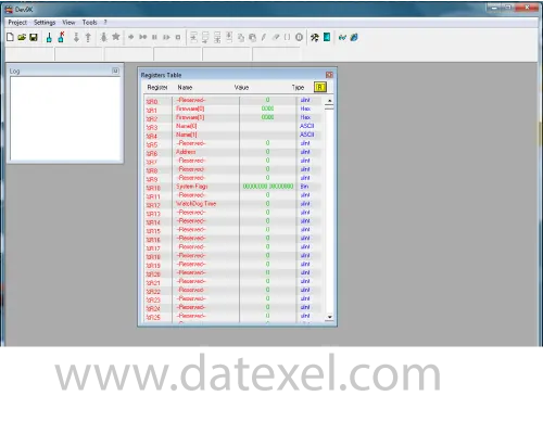
Logged data can be retrieved by removing the microSD/USB drive for analysis or via the Ethernet port to access saved values without interrupting operation. Configuration is performed with Datexel’s DEV9K software (free of charge), which streamlines register mapping, processing rules, and communication settings.
| INPUT | OUTPUT | POWER SUPPLY |
|---|---|---|
| Modbus Master/Slave RS485 | Modbus TCP Ethernet 10/100T | Power Supply Voltage 10-30Vdc |
| Modbus TCP Ethernet 10/100T | Modbus Master/Slave RS485 | Reverse polarity protection 60Vdc |
| CURRENT CONSUMPTION | CONFIGURATION | ISOLATION |
| Between 45 and 80 mA | PC Programmable | Between Input/Comms/Power Supply 1500Vac. |
| EMC | HOUSING | TEMPERATURE |
| For Industrial environments | Material self-extinguishing | Operating Temperature 14°F +140°F -10°C +60°C |
| Immunity EN 61000-6-2 | Dimensions W x H x T 4" x 4 3/4 " x 7/8 " | Storage Temperature -40°F +185°F-40°C +85°C |
| Emission EN 6100-6-4 | 100 x 120x x 22.5 mm | Humidity (non condensing) 0-90% |
| Weight 3 oz 90 g |
| Data Logging: | 1 Micro SD Card |
| Communication: | |
| RS485: | Port 1 Modbus RTU Master, Port 0 Modbus RTU Slave. |
| Ethernet: | Ethernet 10Base-T, Modbus TCP. |
| Power Supply: | Voltage 10 - 30 Vdc. Reverse polarity protection 60 Vdc. |
| Current Consumption: | 80 mA max. |
| Temperature rating: | Operative Temperature -4°F +140°F -20°C +60°C Storage Temperature -40°F +185°F -40°C +85°C. |
| Humidity: | (none condensing) 0-90%. |
| Housing: | Material self-extinguishing. |
| Dimensions: | W x L x H 4 x 4 3/4 x 1inch, 100 x 120 x 22.5mm. |
| Weight: | 7 oz 200 g. |
| EMC. | For industrial environments. |
| Immunity: | EN 61000-6-2. |
| Emission: | EN 61000-6-4. |
| Isolation: | 1500Vac, 50Hz, 1 Minute. |
| Configuration: | PC Configurable. |
| RS-485 | Slave | Master |
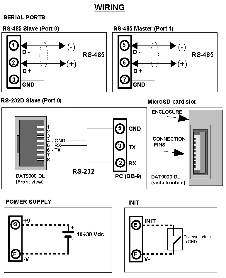
| D- | Port 0 Pin 1 | Port 1 Pin 5 |
| D+ | Port 0 Pin 2 | Port 1 Pin 6 |
| GND | Port 0 GND | Port 1 GND |
| RS-232D | Front view | PC DB9 |
| GND | Port 0 Pin 4 | Pin 5 |
| RX | Port 0 Pin 5 | Pin 3 |
| TX | Port 0 Pin 6 | Pin 2 |
| Power Supply (18-30Vdc). | Positive G Negative F. | |
| INIT | Short pin E to F |
It may be necessary to use an Isolated USB to Serial RS485 Converter as most PC are not Isolated. There are alternative options other than USB to RS485 such as Ethernet to RS485 (DAT3580GW or DAT3580MBTCP). Make sure you have downloaded the USB drives.
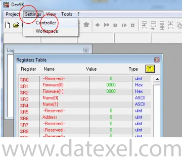
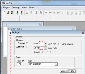
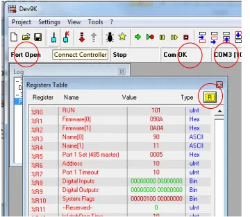
The DAT9000DL adds on-board data logging to removable media, supporting a built-in microSD card and an optional USB flash drive. It records selected internal or polled Modbus registers while retaining the same Modbus RTU/TCP communications and processing capabilities as the DAT9000.
You can flag a register to start logging or set a time-based schedule/interval. In DEV9K, configure a designated control register as the trigger and/or define the schedule for automatic logging.