Modbus RTU Master.

DAT9000
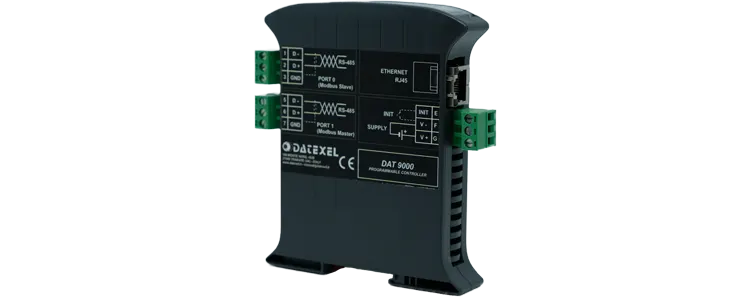
Modbus RTU Master DAT9000.
Modbus RTU Master
• Modbus RTU Master.
• Modbus RS485 Master.
• Modbus RS485, Slave.
• Modbus Ethernet 10 Base-T Modbus TCP.
• Function Block Programming.
General Description

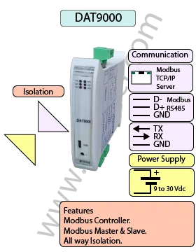
The Modbus RTU Master DAT9000 is a Data Acquisition and controller unit that can be used as a Modbus Master or Modbus Slave. The DAT9000 also has an Ethernet 10 Base-T MODBUS TCP Interface, along with RS485 Master and Slave ports. It is possible to program the DAT9000 to read registers and process logical and mathematical functions, enabling the DAT9000 to provide linearization, scaling, averaging and square root extraction, to name a few. It can be used in conjunction with other Modbus devices. The Modbus RTU Master can be used with a DAT3022 or DAT3024 to provide a 4-20 mA output from a Modbus flow meter or analyzer.

INPUT OUTPUT POWER SUPPLY
Modbus Master/Slave RS485/RS232 Modbus TCP Power Supply Voltage 10-30Vdc
Modbus TCP Modbus Master/Slave RS485/RS232 Reverse polarity protection 60Vdc
CURRENT CONSUMPTION CONFIGURATION ISOLATION
Between 45 and 80 mA PC Programmable Between Input/Comms/Power Supply 1500Vac.
EMC HOUSING TEMPERATURE
For Industrial environments Material self-extinguishing Operating Temperature 14°F +140°F -10°C +60°C
Immunity EN 61000-6-2 Dimensions W x H x T 4" x 4 3/4 " x 7/8 " Storage Temperature -40°F +185°F-40°C +85°C
Emission EN 6100-6-4 100 x 120x x 22.5 mm Humidity (non condensing) 0-90%
Weight 3 oz 90 g

Specifications
Communication:  
RS485: Port 1 Modbus RTU Master, Port 0 Modbus RTU Slave.
Ethernet: Ethernet 10Base-T, Modbus TCP.
Power Supply: Voltage 10 - 30 Vdc. Reverse polarity protection 60 Vdc.
Current Consumption: 80 mA max.
Temperature rating: Operative Temperature -4°F +140°F -20°C +60°C
Storage Temperature -40°F +185°F -40°C +85°C.
Humidity: (none condensing) 0-90%.
Housing: Material self-extinguishing.
Dimensions: W x L x H 4 x 4 3/4 x 1inch, 100 x 120 x 22.5mm.
Weight: 7 oz 200 g.
EMC. For industrial environments.
Immunity: EN 61000-6-2.
Emission: EN 61000-6-4.
Isolation: 1500Vac, 50Hz, 1 Minute.
Configuration: PC Configurable, DIP Switches.
Drawings

DAT9000 Wiring Diagram

Power Supply (18-30Vdc). Positive G Negative F. 
INIT Short pin E to F 
Modbus RTU Master power supply and INIT wiring Diagram.

Modbus Master Slave Port

RS-485 Slave Master
D- Port 0 Pin 1 Port 1 Pin 5
D+ Port 0 Pin 2 Port 1 Pin 6
GND Port 0 GND Port 1 GND
CVPROG Front view Micro USB
Modbus RTU Master and Slave Port.
Applications
Back to General Description
Application Note, PC to DAT9000 connection with an Ethernet cable.
This application note is to connect to a DAT9000 with a Cat5 or Cat6 patch Ethernet cable to a PC.
Printed Version

Very Important.

  1. A crossover cable or Ethernet switch must be used.
  2. The DAT9000 must be on the same subnet mask.
  3. The anti-virus software or firewall may have to be removed.

Setting up the DAT9000.

  1. Connect power to the DAT9000 Modbus RTU Master Controller.
  2. Connect CAT5 or Cat6 crossover cable to the Ethernet port and PC.
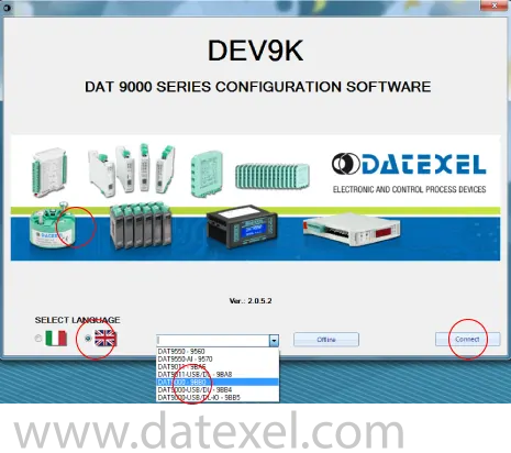
  3. Download Dev9K Version 2 software from Datexel download page and run software.
  4. Select English.
  5. Select the correct version of DAT9xxx hardware from the drop down menu.(this is important). I it must match the label on the side of the DAT9xxx.
  6. Click Connect.
Connecting to the Dev 9K V2.

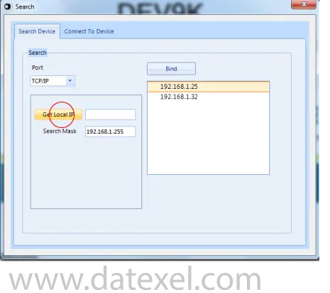
Search for the PC IP Address.

  1. Click Get Local IP.
  2. This will display the Local IP Address of the PC.
  3. If the Local IP Address is not in the same subnet mask as the DAT9000 the local IP (computer IP Address) must be changed. See below for help. Otherwise communication cannot be established.
  4. It is possible to change the IP Address of the DAT9000 later after communication has been established.
Search for the Modbus Master.

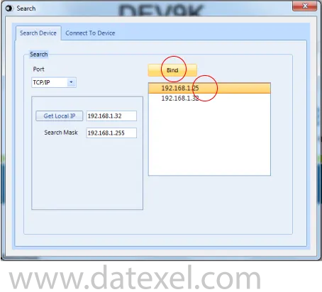
Binding the PC Address.

  1. In the area under the “Bind” button, the networks available on PC are displayed. Select, if listed, the linked network to which the IP Address belongs.
  2. Click on “Bind” button to set the network that will be used to search the device.
Binding the IP Address of a Modbus Master.

Search for the DAT9000

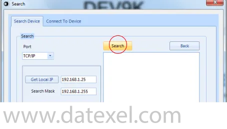
  1. Click on “Search” button to search for the DAT9000 over the network.
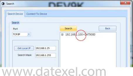
  2. The IP Address of the DAT9000 should appear.
Search for the Modbus Controller.

Search result

  1. Select the IP Address of the controller.
The IP Address appears.

Set the DAT9000 as controller

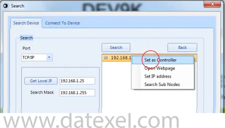
  1. Right click the mouse button and select “Set as Controller” to connect to the DAT9000.
  2. Now the program should start and you can start to build your project or configure the communication settings.
Setting the DAT9000 as the Modbus Controller.

How to change the IP Address of the PC

  1. If the DAT9000 is not in the same subnet of the PC, change the IP Address of the PC to be in the same subnet as the DAT9000.
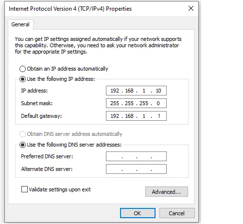
  2. To do this, open the “Network and Sharing Center” section of the operating system in use, go to the PC IPV4 network properties window and configure the network parameters to IP Address 192.168.1.10 Subnet mask 255.255.255.0. default gateway 192.168.1.1
  3. Click OK.
  4. You should now return to search for the DAT9000 section and complete the process.
  5. If you need to change the IP Address of the DAT9000 first make the connection by following the above procedure and then select the tools tab and then the config tab in the dev9k software.
  6. Please note once you have changed the DAT9000 IP Address you will have to change the Address of the PC again.
Setting up ethernet connection to a Modbus RTU Master.

Troubleshooting

  1. Cross over cable must be used.
  2. Both the PC and the DAT9000 must be on the same subnet mask.
  3. Check the cables are plugged in and there is power to the DAT9000.
  4. The default Address of the DAT9000 is 192.168.1.100. If this has been changed and you don’t know what it is, use the INIT function to temporally reset it to the default Address.
Application Note, Introducing DEV 9K Version2 with converting four Modbus Flow meters to 4-20 mA.

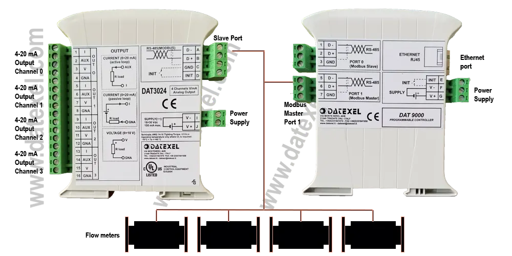
This application is converting four RS485 Modbus RTU Flow meters to four 4-20mA outputs using a Modbus RTU Master Controller DAT9000 and a Modbus RTU to 4-20mA Converter DAT3024.

Printed Version

Start-up.

  1. It is important that you identify the Address, Baud rate, Parity, and Stop bit of the Flow meters. They must all be the same. Identify the actual register which stores the flow rate.
  2. You can connect to the DAT9000 V2 with Ethernet, uUSB or on the RS485 Slave port. For this application we have decided to connect with the Ethernet Port using a cross-over Cat-5 cable.
Application note for Converting 4 Modbus Flow meters to 4-20mA

Wiring connections for DAT3024, DAT9000 and Modbus Flow Meters.

  1. Connect power to the DAT9000 Version 2 Modbus RTU Master Controller, DAT3024 Modbus RTU to 4 channel 4-20 mA output converter and the Flow meters.
  2. Connect the DAT3024 and the Flow meters Modbus Slave ports to the DAT9000 Modbus Master Port.
  3. Connect Cat 5 crossover cable to the Ethernet port and PC.
  4. Connect a multimeter to 4-20 mA output channel 0.
  5. Download Dev9K Version 2 software from Datexel download page and run software.

Connecting to the Dev 9K V2.

  1. Select English.
  2. Select DAT9000 from the drop down menu.
  3. Click Connect.
Connecting to the Dev 9K V2.

Search for the Modbus Master.

  1. Click Get Local IP.
  2. This will display the Local IP Address of the PC.
Search for the Modbus Master.

Bind the IP Address.

  1. Click on the IP Address of the network of the DAT9000.
  2. Click Bind.
Binding the IP Address of a  Modbus Master.

Search for the Modbus Controller.

  1. The Search Button should appear.
  2. Click Search.
Search for the Modbus Controller.

The IP Address appears.

  1. The IP Address on the DAT9000 should appear along with the identification of the DAT9000 module.
  2. If the IP Address does not appear turn off the virus protect or firewall and check that you have a cross-over cable.
The IP Address appears.

Set as Controller.

  1. Right click “Set as Controller.
  2. The Program page should now open.
Setting the DAT9000 as the Modbus Controller.

The Control screen opens.

This is the main control screen for the Dev 9k Version 2. From here you can configure the Communication ports. Design and save new projects and open existing projects. In the left panel you have the function blocks. The center is the layout page for the program with the START position. On the right panel you have the registers. By Clicking the Refresh you can see what is stored in the registers.
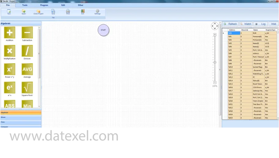
dev 9k version 2 control screen.

Set the Communication port.

The Modbus Controller can only communicate with the Flow Meter and the DAT3024 if all the Modbus ports have the same Communication settings and different Addresses. The DAT9000 will be the Master so Port 1 (RS485 Master) needs to be set up.
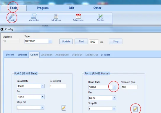
  1. To change the Communication settings of the DAT9000 Master port click Tools.
  2. Click Config.
  3. Change the settings to conform to the Flow meter and the DAT3024.
  4. The Flow meter and the DAT3024 are set at 38400 Baud Rate.
  5. Click the pencil to write to the DAT9000.
Setting up Modbus Master communication port.

Start to design the program.

It is best to break down the project into parts. The first part will be to obtain the flow reading from one of the Flow Meters. The Flow Meter has Address 20( your flow meter will have a different Address), we are going to read register 40015 and place into the DAT9000 on register 35. We will be using a Read Input and must remove 40001 from the register table so the actual Register we use on the read Input Function Block will be 14.
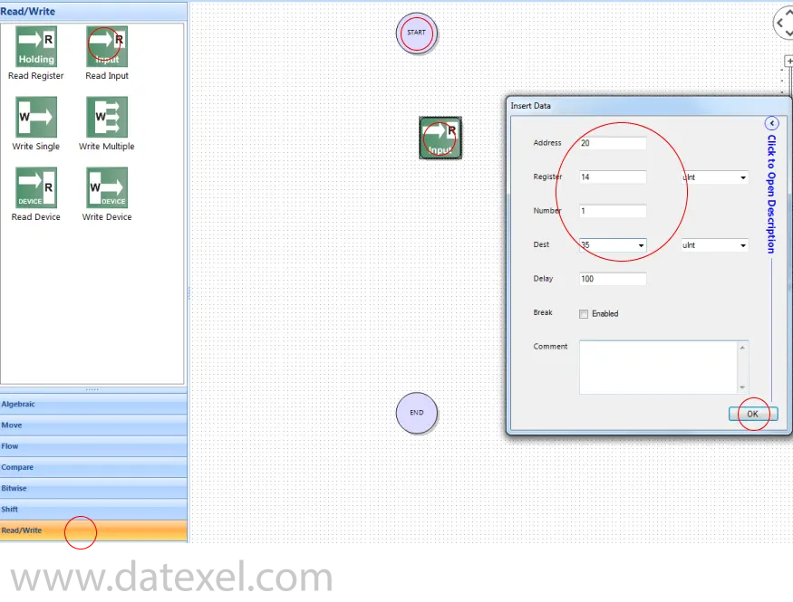
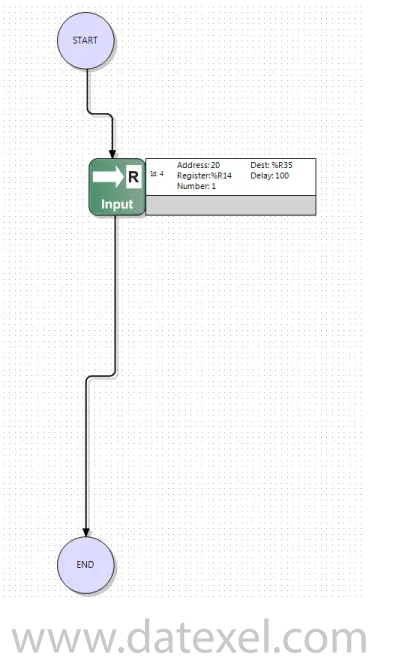
  1. Click the Read/Write label on the lower left panel.
  2. Drag the Read Input Function block to below the Start Icon.
  3. The Insert Data Block will open and you can enter the data needed to obtain the Register.
  4. Address 20, Register 14, Number 1 (we only need the flow input register), Dest 35 (we will store the register reading in Register 35 on the DAT9000) Click OK.
Design the modbus flow meter to 4-20mA program.

Complete the first stage of the project.

  1. Hover over the bottom of the Start circle until a hand is present and pull the line generated down to the Read Input function block.
  2. Do the same from the Read Input Function block to the top of the End circle.
  3. Click Compile and OK.
  4. Click File.
  5. Click Save.
  6. Save as flow-read.
Reading the Flow Meter register and storing in the Modbus Master.

Downloading the program to the Modbus Master.

  1. Click Program.
  2. Click Connect if not connected to the DAT9000. It could have timed out. The bottom of the panel should say Connected.
  3. Click Debug.
  4. Now the Download is visible and click “Download”.
  5. Accept the download twice.
  6. Click Release.
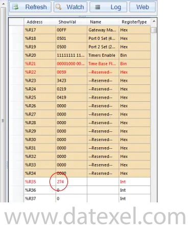
  7. Click Refresh and there should be a reading in %R35. As the Flow changes so should the reading in Register 35.
  8. Should no reading be present in R35 check the communication port settings or wiring.
Showing the flow in the Modbus Master internal register.

Second stage of the project.


Scale function block.

  1. Delete the line from the Read Input to the end.
  2. Click Algebraic on the bottom left panel.
  3. Drag out Scale function block (bottom function block).
  4. The Insert Data block should open.
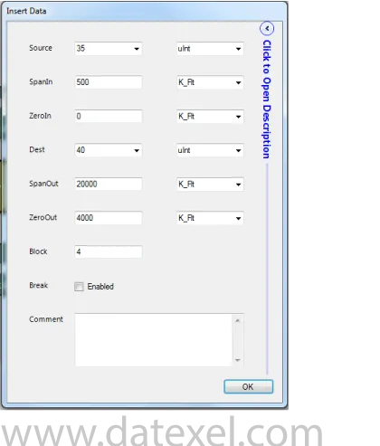
  5. Enter 35 in the Source box ( this is where the flow is stored on the DAT9000).
  6. Set the Spanin to the 500 (or whatever the span is of your flow meter).
  7. Set Zeroin to 0 (or whatever the zero is of your flow meter).
  8. Set Dest to 40, the location of the scaled output.
  9. Set Span Out to 20000. This is equal to 20.000 mA.
  10. Set Zero Out to 4000. This is equal to 4.000 mA.
  11. Block 1. We are only writing to 1 block.
  12. Click OK.

If using a DAT9011 to provide the analog output.

Change the Dest (destination register) to 32 for output 0 or 33 for output 1. There is no need for the Write function block.
Setting up Modbus Master scale function.

Write function block.

The write function block writes the 4-20 mA to the DAT3024 Modbus RTU.
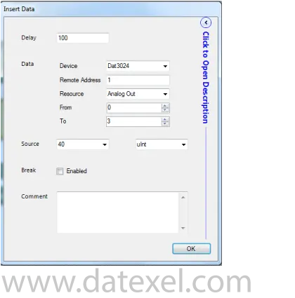
  1. Click the Read/Write label on the bottom left panel and drag out Write Device.
  2. Select the DAT3024.
  3. Remote Address is 1. The Address of the DAT3024.
  4. From 0 can stay.
  5. To 3 can stay.
  6. Source is the 40 where we stored it in the Scale Function Block.
  7. Click OK.
Writing function block from modbus master to modbus slave.

Check the 4-20mA output.

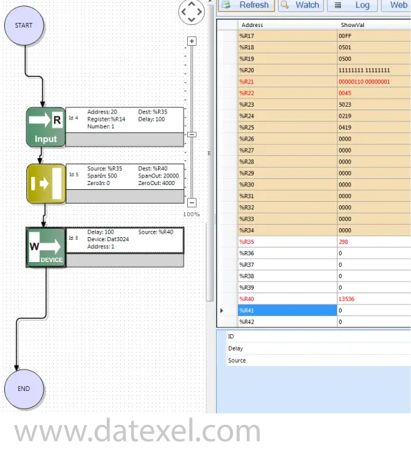
  1. The three function boxes are complete. Save the project, connect again to the DAT9000 and download the project and release.
  2. Register 35 indicates 298 which is the flow rate from the Flow meter.
  3. Register 40 indicates 13536 which is the output from the scale function block and indicates the 4-20 mA output times 1000. The 13536 equals to 13.536 mA and this register is written into the registers in the DAT3024. The multimeter on the output of the DAT3024 Modbus Slave reads 13.56 mA.
Showing and checking the flow and 4-20mA output registers.

Third and final stage.

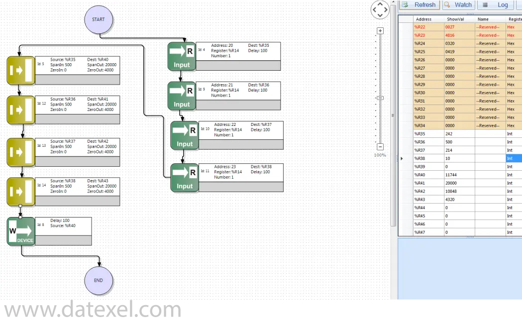
  1. Add 3 more Input registers, 1 for each off the additional Flow Meters.
  2. Add 3 more Scale Function Blocks.
  3. Save the project and download and check the operation. In the diagram you can see the registers with the correct readings and calculations.
Complete project with 4 input register reading and 4 output register on the Modbus Master.

Explanation of the Project.

Back to General Description